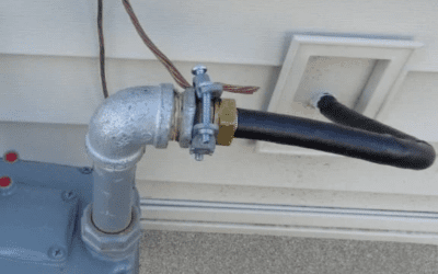
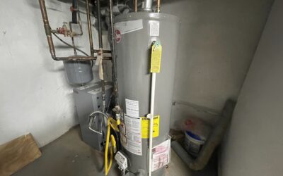
Today, in this guide, we will show you how to calculate gas pipe sizing simply and correctly!
Determining gas pipe sizing is one of the most important steps before installing gas pipes in every building. However, different methods can be used for this calculation. Which method is the best, and how can gas pipes be sized accurately?!
This article will help you answer this question. Let’s get started!
The Importance of Proper Gas Pipe Sizing
Proper gas pipe sizing is like fitting the correct key into a lock. It ensures a smooth and efficient flow of gas to our household appliances. Consider your cozy home kitchen; if the gas pipe supplying the stove is too small, the flame on your burner might flicker weakly, making cooking a time-consuming task. Imagine a reliable hot water heater that suddenly struggles to provide warm showers due to improper sizing.
By accurately sizing residential gas pipes, we create a harmony where gas reaches our appliances at the correct rate, ensuring they operate efficiently, effectively, and safely.
It’s not just about comfort; it’s about making our homes function seamlessly and securely.
Understanding Factors Influencing Gas Pipe Size
Let’s begin with the most important factors that account for sizing gas pipes:
1. Type of Gas: Natural Gas, Propane, etc.
The type of gas transported through a pipe significantly influences its size. Natural gas and propane, for instance, have different energy densities and flow characteristics. Therefore, you must understand the specific gas type to determine the appropriate pipe size for an efficient and safe delivery.
2. Pressure Levels in the System
The pressure levels within the gas system play a pivotal role in sizing the pipes. Higher pressure requires larger pipes to accommodate the increased flow, while lower pressure systems may utilize smaller pipes. Balancing the pressure within the system is necessary to avoid issues such as inadequate gas delivery or excessive pressure that could lead to equipment damage.
3. Flow Rate[1] and Gas Demand
Other key factors in determining gas pipe sizing are the anticipated flow rate and overall gas demand. Appliances with higher gas requirements, such as high-capacity heating systems, require larger pipes to meet their demand. Accurate flow rate calculations help prevent issues like insufficient gas supply, ensuring that all appliances function optimally.
4. Length of the Pipe Run
The distance gas travels through pipes, known as the pipe run, directly impacts sizing. Longer pipe runs contribute to pressure drops due to friction, necessitating larger pipes to maintain adequate flow. Understanding the length of the pipe run is essential for preventing energy loss and ensuring consistent gas delivery throughout the system.
5. Number and Type of Fittings
Fittings like elbows and tees introduce additional resistance to gas flow. The more fittings in the system, the more significant the impact on pressure and flow. You must consider the number and type of fittings to accurately determine gas pipe sizing to compensate for potential restrictions and ensure optimal performance.
6. Local Codes and Regulations
Compliance with local codes and regulations is non-negotiable in gas pipe sizing. Different regions may have specific requirements regarding safety, material standards, and sizing methodologies. Adhering to these codes is essential for ensuring the safety of the gas system and maintaining compliance with legal standards, making it a critical factor in the overall sizing process.
Sizing Gas Pipes with the Longest Length Method
The Longest Length Method is one of the common approaches used in sizing gas pipes to ensure an adequate flow of gas within a system. This method considers the length of the longest gas pipe run in the system, acknowledging that the pressure drop is most significant in this section.
In what follows, we will explain the Longest Length Method. We will walk you through the steps by calculating gas pipe sizes for the below system.
Figure 1: The Gas Distribution Design for a Small Building
1. Calculate the Gas Demand of all Appliances
First, you need to know the appliance’s gas demand. Appliances with higher demand require a larger pipe diameter to ensure an adequate gas supply.
To determine how much natural gas (measured in cubic feet per hour) your appliances use, you take their total BTU rating and divide it by a number. This number is 1,100, roughly the average amount of heat you get from one cubic foot of natural gas.
If the manufacturer specifies the gas demand of the appliance, use that number. Otherwise, you can use the table below.
Table 1: Approximate Gas Input for Typical Appliances
Using the above Table, the maximum gas demands for the appliances in our example are as follows:
- Outlet A (30-gallon automatic water heater): 32
- Outlet B (gas refrigerator): 3
- Outlet C (Range): 59
- Outlet D ( 150,000 btu/h furnace): 150,000/1,100 = 136
2. Identify the Longest Run
Next, identify the longest continuous run of gas pipe in the system. The longest continuous run is the path that the gas takes from the source (gas meter) to the farthest appliance or outlet. This run may include horizontal and vertical sections and any branches.
In our example, the longest run is:
10 + Sec 1 (10) + Sec 2 (10) + Sec 3 (30) = 60 ft
Figure 2: The Longest Gas Run
3. Determine the Equivalent Length
The next step is to calculate the equivalent length of the gas pipe run. The equivalent length accounts for the combined length of all straight pipe sections and the additional length added for fittings and valves.
Each fitting and valve introduces a certain amount of resistance, converted into an equivalent length of straight pipe. Below are the equivalent lengths for different fittings and valves.
Please note that we usually skip this step for residential buildings. This step is effective for large buildings with long gas runs and many fittings.
Table 2: Equivalent Lengths of Pipe Fittings and Valves
Our example is a small building, so we don’t calculate the equivalent length.
4. Use Gas Pipe Sizing Charts
Once the equivalent length is determined, use gas pipe sizing charts provided by relevant codes or standards, such as the International Fuel Gas Code (IFGC) or the National Fuel Gas Code (NFPA 54), to determine sizing.
These charts correlate the equivalent length with the required pipe diameter based on the anticipated gas flow rate and pressure drop.
Now, the question is how to anticipate these amounts.
We conservatively consider 0.5 in. w.c. (inches of water column) pressure drop for iron pipes. Also, most residential gas pipings have a pressure of less than 2 psi (pound per inch), so we use the Table below.
Table 3: Iron Pipe Sizing Table
Look up the total length of your gas pipe in the left-hand column of a gas pipe sizing table. If the exact length isn’t there, choose the next longer length listed.
5. Check the Gas Demand for the Farthest Appliance
In the same row you found the pipe length, look for the gas demand of the appliance farthest from the meter. If the exact demand isn’t listed, choose the higher number in that row.
6. Read the Pipe Size
Look at the top of the column you used in step 5. This column will tell you the correct size pipe for that section.
In our example, the longest run is 60 feet, and the gas demand of the farthest appliance, outlet A, is 32. 32 does not exist in that row, and the higher number is 65. So, the gas pipe size for that is ½ inch.
Figure 3: Showing How to Find the Gas Pipe Size
7. Repeat for All Appliances and Pipe Sections
For all the appliances, repeat steps 5 and 6.
Using the longest run length of the gas pipe system you calculated earlier, look for the appliance gas demand in that row and read the gas pipe size in that column.
For sizing pipe sections, add up the gas demands of all the section’s appliances. Use this total demand to find the correct pipe size for that section in the table (same way as before).
Table 4: Gas Pipe Size Calculations in Our Example
|
The Pipe Section |
What the Pipe Supplies |
Required CFH |
Gas Pipe Size |
|
|
Outlet A |
Water heater |
32 |
½ |
|
|
Outlet B |
Refrigerator |
3 |
½ |
|
|
Outlet C |
Range |
59 |
½ |
|
|
Outlet D |
Furnace |
136 |
¾ |
|
|
Sec 1 |
A and B |
35 |
½ |
|
|
Sec 2 |
A, B, and C |
94 |
¾ |
|
|
Sec 3 |
A, B, C, and D |
230 |
1 |
|
8. Repeat for other Branches
For any other branches coming off the main line, repeat steps 4 through 7.
Other Methods for Calculating Gas Pipe Size
In the following, we introduce two less common methods for gas pipe sizing but don’t explain them in detail.
If you want to know more about these two methods, let us know in the comments, and we will explain them in future articles.
1. The Branch Length Method
The branch length method for gas pipe sizing is a systematic approach to determining the appropriate size of gas pipes in a distribution system. This method is for more complex gas distribution systems. Here’s how it works:
- The first step is to divide the gas distribution system into individual branches. Each branch represents a system segment that serves a particular area or set of appliances.
- Once the system is divided into branches, you need to calculate the gas demand for each branch.
- With the gas demand for each branch known, you can refer to sizing tables to determine the appropriate pipe size for each branch.
- Once the individual branches are sized, the next step is to determine the size of the main supply line that will feed gas into these branches.
2. Manual Calculations
Finally, the last method is manual calculations using formulas provided by IFGC.
In this method, the pipe diameter for rigid iron pipes can be calculated using the following formulas:
- Low-pressure gas equation [Less than 11/2 pounds per square inch (psi)]:
- High-pressure gas equation [11/2 psi (10.3 kPa) and above]:
Where:
D = Inside diameter of pipe, inches (mm).
Q = Input rate appliance(s), cubic feet per hour at 60°F (16°C) and 30-inch mercury column.
P1 = Upstream pressure, psia (P1 + 14.7).
P2 = Downstream pressure, psia (P2 + 14.7).
L = Equivalent length of pipe, feet.
ΔH = Pressure drop, inch water column (27.7-inch water column = 1 psi).
Cr and Y values for natural gas and undiluted propane at standard conditions:
|
GAS |
Equation Factors |
|
|
Cr |
Y |
|
|
Natural gas |
0.6094 |
0.9992 |
|
Undiluted propane |
1.2462 |
0.9910 |
CSST Pipe Sizing Charts
If you have a CSST gas line, use the above method to calculate gas pipe size. Otherwise, follow the manufacturer’s specific sizing tables.
You can find pipe sizing tables for some manufacturers below:
Conclusion
In conclusion, gas pipe sizing is essential for a gas distribution system to work correctly. Small pipes may not deliver enough gas to appliances and cause problems like cold water while showering. On the other hand, unnecessary large pipes can cost you extra money.
Remember, safety is paramount when dealing with gas systems. Do not attempt DIY gas piping work. The safest and most responsible approach is to involve a qualified professional throughout the process. They can assess your specific installation, recommend appropriate pipe sizes for both iron and CSST based on codes and best practices, and ensure a safe and compliant gas system.
We at Matrix Company Solutions Corp. ensure that not only the gas work but also all aspects of a home renovation are done by professionals. Safety, Quality, and Convenience are the signatures of our work!
If you need such renovation work in Philadelphia or New Jersey, book your FREE Consultation Now!
[1]Gas flow rate refers to the volume or quantity of gas that passes through a specific point within a given period of time. It is typically measured in units such as cubic meters per hour (m³/h) or cubic feet per hour (CFH).


![Philadelphia Sump Pump Installation Requirements [2025 Guide]](https://matrixgc.com/wp-content/uploads/2025/06/Philadelphia-Sump-Pump-Installation-Requirements-2025-Guide.png)


The pipe sizing charts are in CFH. The sizing exaple is CFM???
Tom
Thank you for catching that! It was a typo—both the charts and the sizing example should reference CFH. I’ll correct it right away to avoid any confusion. I appreciate your attention to detail!